LED Driver
Entwicklung eines PWM-LED-Dimmers mit einer vierschichtigen Leiterplatte, 2020 — eine Elektronik-Einführung, die zur Ambient-Lighting-Steuerung wurde.
Ich bin kein Elektroingenieur
Während der Arbeit am Ambient Light Projekt stand ich vor der scheinbar simplen Aufgabe, eine LED zu dimmen. Das dafür benötigte PWM-Signal sollte so direkt wie möglich und ohne unnötige Zwischenkomponenten erzeugt werden. Die perfekte Übung für erste Elektronik-Erfahrungen. Zunächst: Ich bin kompletter Anfänger und habe keinerlei professionellen Hintergrund in diesem Bereich. Dennoch stellte ich fest, dass die Erstellung von Leiterplatten einen viel einfacheren Planungs- und Fertigungsprozess sowie bessere Reproduzierbarkeit ermöglicht. Mit dieser Zusammenfassung möchte ich anderen Designer·innen helfen. An dieser Stelle ein großes Dankeschön an Elias Mack, einen echten Elektroingenieur, der mir mit seinem Fachwissen enorm geholfen hat.
Was ist PWM
Wie erwähnt braucht das Dimmen einer LED ein PWM-Signal. Aber was ist das? Vereinfacht gesagt: eine Rechteckwelle mit zwei diskreten Zuständen. An und aus. Die Dauer der Ein- und Ausschaltphase – auch Tastverhältnis genannt – lässt sich über ein Potentiometer steuern. Um dieses Signal zu erzeugen, bauten wir einen astabilen Multivibrator mit einem NE555 Timer-IC als Kern. Mit handelsüblichen Widerständen, einigen Kondensatoren und einem 10kΩ Potentiometer erstellten wir die Schaltung wie im CircuitJS Sketch unten gezeigt. Details würden den Rahmen sprengen, aber mehr Informationen gibt es hier.
Um das maximale Tastverhältnis zu begrenzen, bauten wir einen 2,2kΩ Widerstand ein. Je nach Anwendung ist dieser Widerstand möglicherweise nicht nötig. Das Ausgangssignal geht an eine Treiberstufe, die den Strom zur LED über einen Mosfet steuert. Je nach Anwendungsfall kann die Struktur der Treiberstufe natürlich variieren. Der LED-Vorwiderstand von 7,5kΩ sollte ebenfalls an das verbrauchende Gerät angepasst werden. Wird z.B. ein DC-Motor gesteuert, sollte eine H-Brücke verwendet werden...
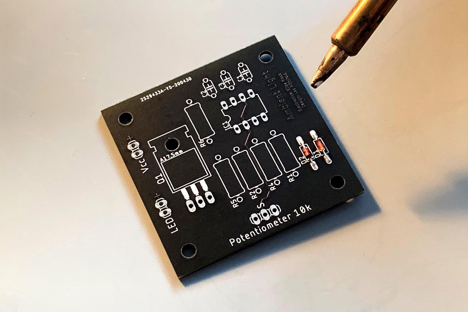
PCB-Herstellung
Nach der Komponentenwahl und Tests auf einem Breadboard können wir die Komponenten entweder auf eine Lochrasterplatine löten oder eine Leiterplatte herstellen lassen. Der Vorteil einer Leiterplatte: einfacheres Löten und bessere Reproduzierbarkeit. Wenn möglich, sollten diese Platinen regional gefertigt werden. Gerber-Dateien lassen sich beispielsweise mit der Autodesk® Software Eagle erstellen.
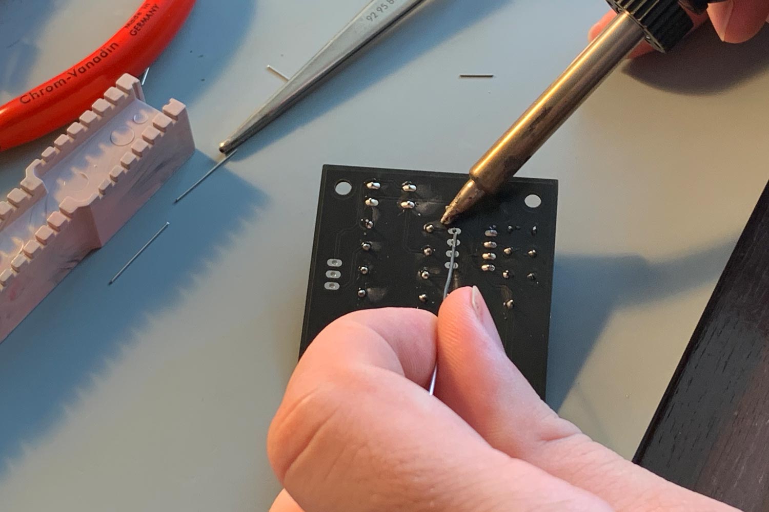
Komponenten löten
Zum Löten der Komponenten braucht man ruhige Hände, einen Lötkolben (idealerweise mit Temperaturregelung), bleifreies Lötzinn, Entlötlitze und optional eine Leiterplattenhalterung. Den Lötkolben auf die am Lötzinn angegebene Temperatur aufheizen. Niedrige Komponenten zuerst. Die Komponenten mit einer Biegelehre auf die richtige Lochgröße biegen und so weit wie möglich einstecken. Bei eingesetzter Komponente die kleinen Drahtbeine umbiegen, damit die Komponente nicht herausrutscht. Jetzt die Leiterplatte umdrehen und das Kupferpad auf der Unterseite etwa drei Sekunden erwärmen. Lötzinn an die Lötstelle bringen und warten, bis das Zinn um den Komponenten-Pin und die Kupferplatte fließt. Dann Lötzinn wegziehen und – kurz danach – den Lötkolben. Warten bis die Stelle abgekühlt ist, überschüssigen Draht abkneifen und fertig! Ich bin selbst kompletter Anfänger und hatte viel Hilfe von Elias Mack bei diesem Projekt. Glücklicherweise gibt es viele Tutorials dazu.
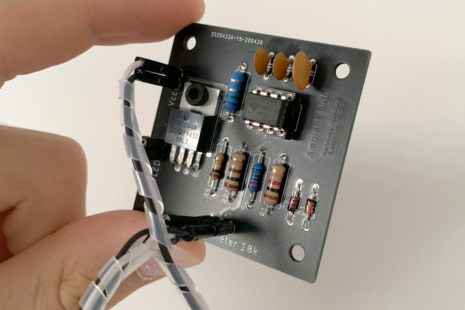
Fertig!
Jetzt müssen nur noch alle externen Komponenten wie Potentiometer, LED und Stromquelle an die Platine angeschlossen werden. Damit haben Sie eine zuverlässige und reproduzierbare Schaltung.


